pantograph design calculation
Now you have to choose a stylus that will at least enter the form in the model. Such could be accomplished with any stylus and any cutter merely adapting the pantograph ratio to get the size desired.
Multibody Modeling And Nonlinear Control Of The Pantograph Catenary System Springerlink
The Computer-Aided Design CAD files and all associated content posted to this website are created uploaded managed and owned by third-party users.

. Temperature rise generated when currents required by subsidiary facilities in vehicles pass through pantograph and overhead. Pantograph measurements and the evaluation of the catenary condition can be made with regular railway engines equipped with measurement systems during normal operation. Download Citation Raising Torque Calculation System Design for Single-Arm Pantograph Raising torque is one of the import parameters when we design pantograph.
Siemens Mobility performs the entire development process including design construction calculation simulation prototype building and production in Austria. Optimization design requirement for pantograph limit height is 3000mm and the time of rising pantograph controls within 6s. When electric trains stop pantograph and overhead contact line contact points are relatively at a relative standstill position.
Completed oil painting from small photograph shown at end of video. The following is the simulation image of rising pantographs height. How we can calculate raising.
Measurements should include values such as vertical contact force vertical acceleration and sideway position calculation from contact forces. The scale factor is the ratio frac text distance from the fixed point to the drawing point text distance from the fixed point to the tracing point. In a Python 3 shell create a PantoGraph instance using the values you noted earlier.
The design of pantograph and overhead contact line systems should minimize abrasion of two vibration subsystems in operation. The pantograph is fitted on a thread shaft which is supported on two bearings the pivot joint is fitted onto a wooden bracket with a 6 mm pin the bracket is then fitted to the support bearing frame which is bolted to the main frame this feature permits it to be moved forward and backwards by rotating the hand nut on the right of the thread shafting it could be move. Now draw a rectangle or circle with a simple notch or a cove in it.
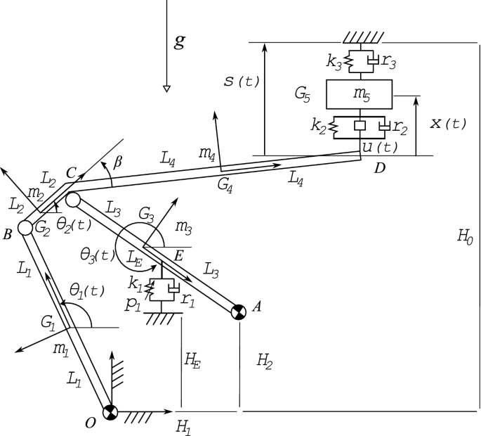
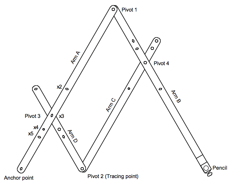
It is often suitable to connect the definition of the dynamic system to a CAD-tool where it is easy to define geometry calculate mass and inertia position of joints and loads etc. The fixed pivot pointer and pencil must be rigid and with pivot c be of such a length that the pantograph as a whole moves parallel to the paper. Pantograph Video 2 showing mathematical process to enlarge a small photograph to a large canvas for painting.
Therefore this project is aimed at developing a Pantograph mechanism which can be used to magnify the smaller shapes on the sheet metals. Each CAD and any associated text image or data is in no way sponsored by or affiliated with any company organization or real-world item product or good it may purport to portray. A little sliding weight to place on the rod near the pencil will be.
And it replaces all the drawing tools on the work table. Three-dimensional CAD models are also suitable for visualisation of the design for investigation of aerodynamic forces animation of the dynamic behaviour etc. From pantograph import pg PantoGraph driver follower motor_1_pos motor_2_pos The servos and arms will move immediately this is why its important to have fastened the arms loosely.
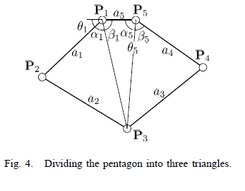
The ability to record and collect all data in database enables. The specially developed hardware-in-the-loop test facility is unique in the world and makes it possible to emulate the interaction between the pantograph and simulated overhead contact line in real time. This page breaks down the triangles pretty well.
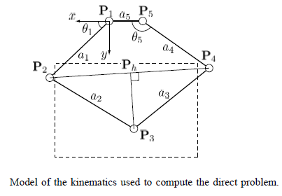
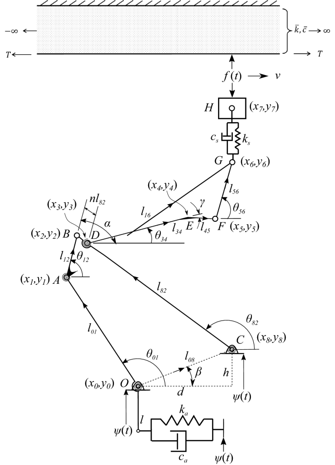
Calculated for different situations. The mechanics of the device serve to keep that ratio constant as the mechanism is rotated expanded andor contracted. The 3 2 3 2 cos 90 sin cos cos 90 sin cos x L b L N L b N L γθ θ α γθ θ α.
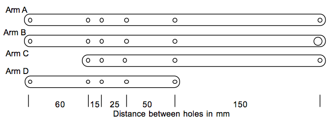
- When adjusting the instrument for reduction or enlargement make sure that the adjustment pivots are in the holes corresponding with the scale.
Design And Control Of A Pantograph Robot Northwestern Mechatronics Wiki

Geometry How Can I Adjust A Pantograph Equation To Account For An Offset Tip Mathematics Stack Exchange

Panto Graph Mechanism Design Grabcad Tutorials

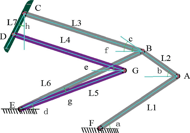
Pantograph Configuration Download Scientific Diagram
Peter S Articles How To Build A Pantograph

Pantograph Model And Geometry Of The Frame Download Scientific Diagram
Design And Control Of A Pantograph Robot Northwestern Mechatronics Wiki
2

Panto Graph Mechanism Design Grabcad Tutorials
Graphical Representation Of A Pantograph Model A Two Dimensional Download Scientific Diagram

Pantograph And Catenary System Download Scientific Diagram
Peter S Articles How To Build A Pantograph

A Pantograph Of Two Masses Lateral View Download Scientific Diagram
Parameter Optimization Of Pantograph Structure Based On Multi Objective Genetic Algorithm Springerlink
Pantofun Pantohealth Gmbh

Panto Graph Mechanism Design Grabcad Tutorials

Pantograph Degrees Of Freedom Raising Of The Mechanism Up Left Download Scientific Diagram
Dynamic Interaction Between Multiple Pantographs Sliding On An Overhead Conductor Wire A Multibody And Wave Based Approach Springerlink

Panto Graph Mechanism Design Grabcad Tutorials


Comments
Post a Comment